I follow a number of FB groups and forums about 3D printing in general and the Folger 2020 i3 in particular and questions about auto level keep coming up. The 2020 i3 doesn’t ship with autolevel, but when I ordered mine I thought auto level sounded like something I’d like and Folger sold an inductive sensor for just under $4 so I tossed one in with my order.
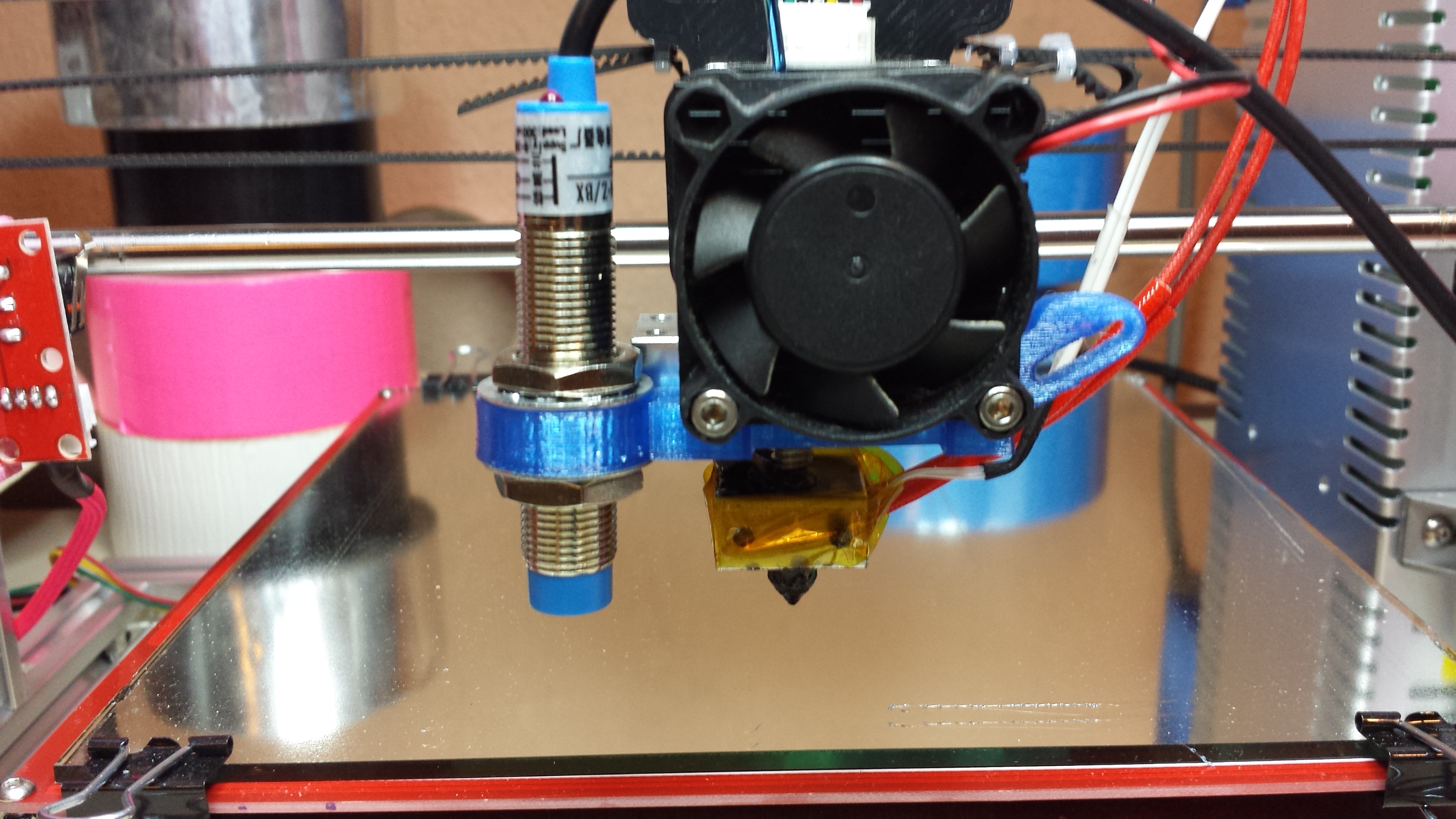
My first inductive autolevel sensor and mount.
Little did I know what I was about to get into. Let’s see if I can make this a little easier for other people than it was for me! After the break I’ll explain what autolevel is and how it works as well as share my experiences setting it up and using it.
What is autolevel?
Ok, so first off what’s commonly called auto level isn’t quite what it sounds like. It doesn’t level the bed for you automatically. Instead what it does is measure how out of level your bed is and then mathematically model it so the printer can compensate by adjusting the z axis while printing so layers stay even even if the bed isn’t 100% level. This means there’s a lot more work going on for your Z axis than normally where it only runs to shift things when you change layers. As a result I decided to upgrade my machine to use lead screws before adding auto level – but lead screws would be another topic for another post! Even with lead screws I still like to manually level my bed pretty close so the auto level only has to make minor corrections. But even with my bed as level as I can get it manually the auto level routine still does an impressive amount of correction.
So to set this up there are two things to address. First the printer needs a way to measure the bed so we’ll have to add some extra hardware. Second the printer needs to be configured to use that hardware and make the necessary calculations – so there’s a software component as well. Neither is particularly simple but there are more options for Hardware so I’ll address it first.
Hardware
There are a lot of different ways to measure the bed. Despite the differences though they generally all consist of removing your Z endstop and instead creating some kind of Z probe that can take readings from different parts of the bed. One common way of doing this is with a servo and a microswitch. The necessary servos are only a few dollars and the microswitch can usually be harvested from the Z endstop. But I’m not a huge fan of this method because it’s a lot of moving parts that can wear and develop slop – too much mechanics for me. Very similar to a servo method is the bltouch sensor which was an indigogo project and is now available on ebay, it’s basically a microswitch on a solenoid that simplifies the mechanics. A big benefit of either of these two mechanical approaches is that you’re actually measuring the surface of the bed directly so changing bed surfaces won’t have an effect on your readings.
The other methods are touchless there are capacitive sensors which like the mechanical sensors measure the top surface of the print bed which is nice…but I’ve used capacitive sensors in the past and found them fiddly to deal with. Another choice is an infrared sensor such as e3d used on the bigbox, but that won’t work with a reflective print bed. The method I chose to go with is an inductive sensor.
The downside to an inductive sensor is that it’s designed to sense dense ferrous metals like cast iron and steel. It will sense aluminum but not as well or from as far of a distance. The sensor I ordered from Folger (a LJ12A3-4-Z/BX) only has a 4mm sensing distance but comes in a nice compact 12mm x 61mm threaded tube package. I found some designs on thingiverse for mounting it but wasn’t entirely happy with any of them so I combined two of them into my own design that doubled as a layer fan mount. I got this sensor working by putting a sheet of 28ga galvanized sheet metal from the local hardware store under my glass so there was something for the sensor to detect. An idea I learned about from this blog by 3DPrintMi which if I hadn’t stumbled across I probably would have gone with a servo setup instead. But with my glass being 3mm thick and the metal not being substantial enough and me running the sensor off 5v for simplicity I didn’t get the full 4mm sense distance and getting things lined up was very fiddly with no room for error. I wound up with the probe barely higher than the nozzle and if anything shifted at all found myself dragging the nozzle into the bed or printing my first layer in the air. Not optimal.
So I ordered a new sensor with a 8mm sensing range. This came in a larger 19mm package and required me to redesign my mount – the new version is still at the same thingiverse link – and while it worked at 5v it didn’t work reliably. So I had to do a bit more work. The new sensor is a LJ18A3-8-Z/BX which like my original sensor is an NPN sensor. For those of you familiar with transistors that will make sense. For the rest I’ll just say that these sensors are basically electronic switches, much like transistors, and come in both PNP and NPN versions – exactly like transistors. Basically a PNP sensor is designed to direct current to convey it’s signal while an NPN sensor is designed to sink current as it’s signal. Because of this running the NPN sensor at 12v is less risky as you’re not sending 12v to your control board. But there is still a 12v potential between the signal line and ground so for safely I still used a voltage divider made up of two resistors to lower the voltage to the 3-4v range since the arduino I use as my controller is only rated for 5v max on it’s pins.
To get the 12v I had to solder an additional header onto an unpopulated set of holes on my ramps board near the fuses. Before hooking the signal wire up to the z min position I powered things up and tested that the sensor did indeed trigger (the light on top will come on when it does) and played around to see how sensitive it was. The 8mm distance sensor running at 12v was MUCH more sensitive. I was now able to remove the galvanized steel from under my glass (which made heating the glass for ABS much easier) and the sensor would trigger directly from the copper in my heated bed – and did so higher off the glass than my original sensor, win! However I soon found that it wasn’t perfect. In fact the new sensor was so sensitive that if I probed the bed over a spot where there was a screw head under the heated bed it would read higher in that spot. To correct this I gave it something right under the glass to detect – a piece of heavy duty aluminum foil. This worked great. The aluminum foil conforms to the bottom of the glass and gives more accurate readings than my old steel sheet which had curled slightly on one edge when I cut it and caused a very slight error in probes of that side.
Software
So with the mechanics out of the way it’s time to address software. The version of Marlin that Folger provides is horribly out of date. Another Folger owner – therippa – shared a pre-configured version of the latest official Marlin release. One notable thing about his configuration is that it moves the X endstop from the right at x-max to the left at x-min. This is important because autolevel only works reliably when you home to x/y min at the front left of your bed. It just doesn’t know how to deal with any other setup and still do the math for autolevel. I went a step further and applied therippas configuration changes to the latest RC3 pre-release of Marlin. (NOTE: my version is slightly different again in that I had already installed lead screws so my Z steps are set to 400 instead of 4000 as you would want for the 5m threaded rod these machines ship with stock.) If you’re interested in just what has to be changed to setup autolevel I’d direct you to this instructible which goes into more detail.
Final setup
Alright, so you’ve got a sensor mounted, you’ve got your software updated and you’re ready to autolevel! Well, not quite. You still need to configure the probe offset which tells Marlin where the new Z probe is in relation to your nozzle. Since an inductive sensor sits higher than the nozzle your Z offset is going to be negative. X and Y should be fairly self-explanatory but Z can be pretty confusing so I’ll walk through how I go about setting it up.
First I make sure that the EEPROM and EEPROM chitchat are enabled in the configuration.h file. This makes it possible to tweak things without having to constantly reflash the arduino board.
Then I manually do a G28 command to home printer. You’l want to be ready to hit the emergency stop button or pull the power to your printer when you do this the first time. If your sensor is too high up you could wind up smashing your print head into the print bed. For this reason if no other I’d suggest leaving the manual leveling springs in place for now – with autolevel you can get rid of them for fixed spacers…but having a bed that can give is nice when you screw up.
If things are setup correctly the printer should home like normal…but instead of dropping the Z at the 0,0 point it should move the probe to the center of the bed and do the Z homing there. When it’s done the nozzle will still be some distance off the print bed.
If you think you’ve got your z offset set correctly and are feeling brave (or stupid) you can test it now by doing a ‘G1 Z0’ command which will drop the nozzle to Z0. I wouldn’t though as your offset is almost certainly not correct yet.
Instead I like to do a ‘G92 Z10’ which tells the firmware that it should consider your Z to currently be 10mm above the print bed. It’s not…we’re lying to the printer here to give ourselves room to work – so be careful it will now gladly let you slam the nozzle into the bed on purpose. What you now want to do is put a piece of ordinary printer paper under the nozzle and to slowly — SLOWLY — lower it until the nozzle just drags on the paper. As you do this keep count of how far you have to move the nozzle. You can now use that value to adjust your Z-offset. Since you started at 0 from the G28 command if it took you 2.8mm to touch the paper you’ll want to set your Z-offset to -2.8 If you have the EEPROM enabled you can do this with a ‘M851 Z-2.8’ command which I usually follow up with a ‘M500’ to save current settings to EEPROM and ‘M501’ to read them back – the last line returned will be your M851 value which should match what you entered.
Now you should be able to do another G28 and when it’s done a ‘G1 Z0’ should drop your nozzle right to where it just touches the paper. If not…issue a new M851 to set the offset slightly higher or lower and try again. Lather, rise, repeat until you’re happy with your Z0 position.
With that good you can then raise the Z a few mm so you don’t scrape anything and issue a G29 which will probe the bed and tell the firmware how out out level you are. If that works you can then add a G29 command to your starting gcode so it runs right after the G28 home command and each print will measure the bed before it starts!
There’s a lot more to it than that…but this could easily be 4 or 5 posts if I went into all the details. Instead of rehashing it all I’d direct you to the instructibe I linked earlier, this excellent video by Thomas Sanladerer, this blog by 3DPrintMI which was where I got the idea to try putting thin steel under the glass, and this blog series by ZennMaster – those were the resources that helped me the most when I was setting up my autolevel.
Tags: 3d printing, auto level, auto tramming, autolevel, diy, electronics, folger tech, projects, prusa i3
Great article. Definitely gonna use this for my 2020 printer.
Do you mind posting the link to your thingiverse file for the 8 mm sensor/print fan? I am not seeing it. Only the pictures of the brackets
You mean the fan shroud? I used the one from the bracket I had based my modifications on: http://www.thingiverse.com/thing:1161013/#files
I don’t use that extruder anymore and never updated the 8mm sensor with the changes I made to the larger version since I had switched to the larger sensor. Also it looks like the original design I based mine on now has a new improved fan shroud option that I haven’t tested since I’ve moved on to this setup: http://www.thingiverse.com/thing:1449709 Though I getting ready to replace that with a geared extruder now 😀
I just have the stock printer with no real upgrades yet, so I’m not sure if the mount that you designed will work for me right off the bat being that I don’t have the upper components to my extruder that I see in the pictures attached to the mount you designed. I will most likely have to settle for a more basic set up at first.
Unless you think that it might work for me? If so, how would I attach it to my extruder?
Oh, I think I see what caused the confusion…looks like I messed up a link in my post and instead of linking to the mount I just linked to a photo of it. Sorry about that. Here’s the link to the mount I designed that works with the stock extruder: http://www.thingiverse.com/thing:1267183
There are several versions in there, one designed for the smaller diameter sensors and a few slightly nicer ones for the larger diameter sensors. They all work and I used them with my stock extruder before I upgraded to the new extruder and hot end.
The versions I just linked to mount between the fan and the heatsink, so you just remove the two screws holding the fan in place, put the mount on, then put the fan back on.
Sorry for the confusion, hope you get your sensor up and going soon!
Oh awesome, exactly what I was looking for! I have the 18mm sensor and will most likely be using the foil method. Seems like a lot less of a pain since I already have the glass anyways. Thanks for the post and replies. I think your folger tech 2020 review kinda pushed me to get this particular printer.
I know I should probably print in abs, but only ordered pla because I’m a noob and didn’t think exactly know the difference at the time of ordering m. So do you think that would work for the time being? im most likely gonna order some abs soon though
PLA for the mount is ok for short term use, but can deform and sag over time due to it’s proximity to the heated bed and hot end. I’ve used both ABS and PETG for most of mine, Personally I prefer PETG to ABS – but with the stock hotend you’ll probably have better success with ABS as PETG tends to like temperatures that start to risk damage to the PTFE liner in the stock hotend.
Big issues with ABS are getting it to stick to the glass and keeping it from warping. As far as sticking I’ve had good luck with aqua net in the purple can. Three light coats allowing them to dry between coats works great for me – ABS/PLA/PETG all stick great while printing then pop right off when it cools. As for warping…unfortunately the best bet there is to encase the printer to hold heat in – but the Folgers steppers and stepper drivers run hot enough that I’m nervous about going that route. So I tend to only print things that aren’t likely to warp in ABS and everything else in PETG/PLA.
would you think most aqua nets would work? or is there something specific about the one you mentioned?
Thanks for all your help! I will be sure to let you know how my experience with the foil and 8mm sensor goes.
Not sure. The purple can was all they had at the store I went to so it’s the one I bought and has worked well for me. I later confirmed that it’s the one others recommend as well. I know that not all hair spray is equal but there’s a lot of debate about just what particular ingredient is key. In general though it seems the higher the “hold” the better and the aquanet is cheap and proven.
I also have some of the purple elmers glue stick but have never tried it since the hair spray has worked so well for me.
In fact, with really good filament like atomic and maker geeks I don’t even bother with the hairspray unless it’s a part with a very small footprint that’s likely to come loose. Just bare glass works well. But with more questionable filaments like folgers generic self-branded I need CLEAN glass with fresh hairspray or even easy things pop off.
My first print has happened! What a sight! Except it wasn’t the perfect thing that I had hoped it to be ha. My stock extruder doesn’t seem to want to hold onto the filament. I posted about my issues on the reprap forum already. I was wondering if you could give me some pointers or if you know of something that I am doing wrong/not doing? Thanks for all your help! Hopefully I can eventually get to the autolevel part.
http://forums.reprap.org/read.php?406,678193
Isaac
Excellent news! I really lucked out on my first print, I was expecting a week or two of troubleshooting, debugging and tuning…but my first print came out REALLY good. In fact it’s still on my printer! (though no longer being used for its intended purpose. It was a mount for a 2004 LCD – and I now use it to keep the wires from my extruder from rubbing against my RAMPS because I’ve yet to make a cable chain 😀
Have you checked that the gear on the shaft of the extruder stepper is tight? It’s a very common problem with these folger extruders for one or both of the grub screws to be loose and for the gear that grabs the filament to spin on the shaft. The only other thing that comes to mind that could cause that is if there isn’t enough tension in the idler…but with the stock extruder there’s no way to adjust that. Which is why I had swapped to a metal extruder I got for $12 off ebay, but that wouldn’t fit a e3d v6 so I swapped again to the extruder I’m currently running. I still need to finish my geared extruder and get it on there…one of these days….
Thanks for the reply!
Yeah I opened up the extruder to really see what was going on and then allowed a cold extrusion through my gcode and this is what I see
https://youtu.be/ny_nYtOwNow
Which explains why nothing is coming out. I have had some serious issue with the 4 pin motor connectors that came with the print I’ve already had to replace one for the y axis and this seemed to be the issue again because I put the x axis connector, which I know works correctly, on the extruder motor and it came out perfectly. So I guess I will be talking to folger tech again and seeing if I can get a new connector.
So close! Yet so far away!
Hairspray and glass worked perfectly by the way!
Thanks for all your help!